
 EN
EN
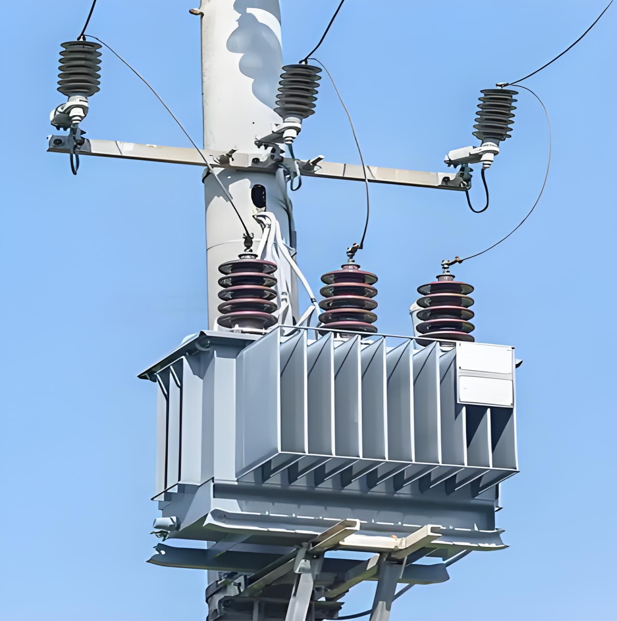
A distribution transformer serves as one of the most critical links between high-voltage transmission networks and the end-users who depend on reliable power. Unlike large power transformers used at generation stations, a distribution transformer is specifically engineered to reduce medium-voltage electricity — typically ranging from 11 kV to 33 kV — down to the low-voltage levels that homes, commercial buildings, and light industrial facilities actually consume. This fundamental role in the last mile of electrical delivery means that the design philosophy behind a distribution transformer must account for a unique and demanding set of conditions that differ substantially from transmission-level equipment.
Designing a distribution transformer for local grid applications requires balancing electrical performance, environmental resilience, regulatory compliance, and lifecycle cost. Every component — from the core material to the cooling system — must be selected and engineered in response to the specific demands of community-level power distribution. Understanding how these design decisions are made helps utilities, contractors, and facility managers choose the right equipment for their infrastructure and ensure long-term operational stability.
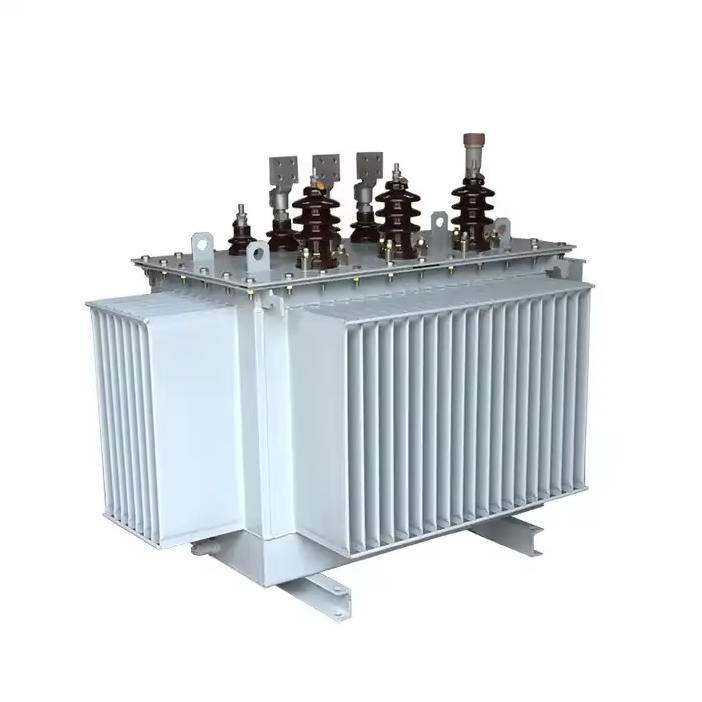
Core and Winding Design Principles
Magnetic Core Selection and Loss Management
The magnetic core of a distribution transformer is the heart of its energy conversion process, and its design directly determines the unit's no-load losses and overall efficiency. For local grid applications, where a distribution transformer may remain energized 24 hours a day regardless of the actual load demand, minimizing core losses is a primary engineering priority. Modern designs predominantly use cold-rolled grain-oriented silicon steel, which offers low hysteresis and eddy current losses compared to conventional hot-rolled materials.
The core is typically assembled in a stacked or wound configuration, with step-lap joints used to reduce magnetic flux distortion at the corners. This technique significantly lowers noise emissions and vibration — a factor that matters greatly when a distribution transformer is installed in residential areas or near commercial establishments. Careful core geometry also ensures that flux density is maintained within safe operating limits across the full range of voltage variation seen in local grids.
Advanced designs may incorporate amorphous metal cores, which offer dramatically lower no-load losses than silicon steel. While the material cost is higher, the energy savings over a typical 20 to 30-year service life often justify the investment, particularly in regions where energy tariffs are high or where regulatory standards impose strict efficiency thresholds on distribution transformer installations.
Winding Configuration and Conductor Materials
The winding design of a distribution transformer must achieve efficient energy transfer while managing heat generation, insulation integrity, and short-circuit strength. Copper and aluminum are the two primary conductor materials used. Copper windings offer lower resistivity, which translates into reduced load losses and a more compact design. Aluminum windings, while requiring larger cross-sections to achieve equivalent conductance, offer a weight and cost advantage that makes them attractive in certain distribution applications.
For local grid service, the high-voltage winding is commonly wound in a layer or disc configuration, while the low-voltage winding uses a helical arrangement to handle higher current densities. The winding geometry affects leakage reactance, which in turn influences voltage regulation under varying load conditions — a critical parameter for any distribution transformer serving an end-user grid where load profiles fluctuate throughout the day.
Insulation between winding layers is achieved using kraft paper, pressboard, or synthetic materials, all of which must be thoroughly dried and vacuum-impregnated before final assembly. This process eliminates moisture and air pockets that could reduce dielectric strength and lead to premature failure in field conditions.
Insulation System and Dielectric Design
Oil-Immersed Insulation in Outdoor Distribution
The oil-immersed distribution transformer remains the dominant technology for outdoor local grid deployment because mineral oil provides both dielectric insulation and thermal cooling in a single medium. The insulating oil fills the tank, saturates the paper insulation around the windings, and circulates to carry heat away from the core and coil assembly. This dual function makes oil-immersed design particularly well-suited for distribution transformer installations in outdoor pad-mounted, pole-mounted, or substation configurations.
Transformer oil must meet specific standards for dielectric breakdown voltage, moisture content, and acidity. During manufacturing, the active part — the core and coil assembly — undergoes vapor-phase drying to remove residual moisture before oil is introduced under vacuum. This procedure ensures that the insulation system achieves its designed dielectric strength and extends the service life of the distribution transformer significantly.
In local grid applications, the oil volume and tank design must also account for thermal expansion. Conservator tanks or sealed tank designs with nitrogen cushions are used to accommodate oil volume changes caused by temperature cycling. Proper management of the oil-air interface prevents oxidation and contamination, which are primary drivers of insulation degradation over time.
Voltage Class and Clearance Requirements
Every distribution transformer must be designed with precise electrical clearances between live parts and grounded structures, as well as between the high-voltage and low-voltage windings. These clearances are determined by the voltage class of the unit, which specifies both the operating voltage and the required withstand levels for lightning impulse (BIL) and applied voltage tests.
For a distribution transformer serving a typical 11 kV local network, the high-voltage winding must be rated for standard impulse withstand levels that account for the overvoltage transients common in distribution grids — including those caused by switching operations, nearby lightning strikes, and capacitor bank energization. Meeting these requirements is not optional; it is a fundamental design constraint that determines the insulation geometry and material selection throughout the unit.
Bushing design also falls within this domain. Outdoor distribution transformer installations use porcelain or polymer bushings rated for the appropriate voltage class and pollution level of the installation environment. In areas with heavy industrial emissions or coastal salt exposure, enhanced creepage distance requirements apply, and the distribution transformer design must accommodate these bushing specifications within its overall terminal layout.
Thermal Management and Cooling System Design
Natural Oil and Air Cooling (ONAN) for Local Grids
The most common cooling method for a distribution transformer in local grid service is ONAN — Oil Natural, Air Natural — which relies entirely on the natural convection of oil within the tank and the passive dissipation of heat from the tank surface to the surrounding air. This cooling mode requires no external fans, pumps, or active cooling equipment, which makes it extremely reliable and maintenance-free in field conditions.
The thermal design of an ONAN distribution transformer centers on the sizing of the tank surface area and the use of corrugated radiator panels or fin-type cooling tubes that increase effective heat dissipation area without enlarging the overall tank footprint. Engineering the thermal gradient between winding hot-spot temperature and ambient air is critical: the hot-spot temperature must remain below defined limits (typically 98°C for paper-insulated windings under IEC standards) even under peak load conditions.
Thermal modeling during the design phase accounts for the geographic and seasonal temperature range of the intended installation location. A distribution transformer designed for tropical environments must handle higher ambient temperatures and may require increased cooling surface area compared to a unit designed for temperate climates. This site-specific thermal engineering is a key reason why distribution transformer specifications should always include the maximum ambient temperature of the installation site.
Overload Capacity and Temperature Monitoring
Local grids often experience load conditions that temporarily exceed the nameplate rating of the distribution transformer. Agricultural irrigation seasons, summer air-conditioning peaks, and industrial shift changes can all create short-duration overloads. Responsible distribution transformer design includes an inherent overload capacity — defined by the thermal time constant of the core and coil assembly — that allows the unit to absorb these surges without immediate damage.
Modern distribution transformer designs increasingly incorporate winding temperature indicators (WTI) and oil temperature indicators (OTI) as standard features. These instruments provide real-time monitoring of thermal conditions and can trigger alarms or automatic load shedding if temperatures approach critical thresholds. In smart grid environments, this data can be transmitted to a control center, allowing utilities to manage distribution transformer loading proactively and extend asset life.
Thermal aging of the insulation paper is a cumulative process that accelerates exponentially with temperature. Every distribution transformer design is therefore governed by a thermal life model that estimates insulation longevity as a function of operating temperature history. Managing this thermal life is one of the central challenges of distribution transformer asset management in local grid operations.
Mechanical Structure and Environmental Protection
Tank Design and Structural Integrity
The tank of a distribution transformer serves multiple functions: it contains the insulating oil, provides structural support for the active part, protects internal components from environmental exposure, and dissipates heat. For outdoor local grid applications, tank fabrication uses steel plate that is welded and tested for oil-tightness, then treated with corrosion-resistant coatings to withstand weather, humidity, and industrial pollutants.
Tank geometry is engineered to ensure that the active part is fully submerged in oil with adequate clearance on all sides, and that internal oil circulation paths are unobstructed. The design must also accommodate the weight and seismic loads appropriate for the installation site, with mounting flanges or base frames sized to match pad foundations or pole brackets used in local distribution infrastructure.
Pressure relief devices are installed on the tank to vent internal overpressure caused by internal arc faults or severe overheating. These safety features are a mandatory element of distribution transformer design and must be sized to respond rapidly enough to prevent tank rupture while minimizing unnecessary oil release into the environment.
Protection Accessories and Grid Integration Features
A distribution transformer for local grid service is rarely delivered as a bare transformer unit. It typically includes a suite of protection and monitoring accessories that enable safe integration into the distribution network. On-load or off-load tap changers allow voltage adjustment to compensate for variations in the primary network voltage and match the secondary output to the requirements of connected consumers.
Buchholz relays are installed in the oil pipe between the main tank and the conservator to detect the gas accumulation that signals internal faults. These devices provide an early warning function that can save a distribution transformer from catastrophic failure if a developing fault is detected and acted upon promptly. Combined with differential protection relays at the substation level, these accessories form a comprehensive protection system that covers the distribution transformer from multiple fault modes.
For a distribution transformer designed specifically for outdoor local grid deployment, the terminal arrangement, earthing provisions, and cable entry points must all be configured to match the network topology and installation method used by the local utility. This integration-focused engineering ensures that the unit can be installed efficiently and commissioned reliably without requiring field modifications.
Compliance, Testing, and Standards Alignment
International and Regional Standards
Every distribution transformer produced for local grid use must conform to recognized national or international standards that define performance requirements, test procedures, and safety criteria. IEC 60076 is the globally referenced standard series for power transformers, including distribution transformers, and covers everything from routine dielectric tests to temperature rise testing and short-circuit withstand verification. IEEE C57 standards serve the North American market with equivalent scope and rigor.
Regional energy efficiency regulations add another layer of compliance requirements. Many jurisdictions now mandate minimum efficiency levels for distribution transformer equipment, expressed as maximum allowable no-load loss (P0) and load loss (Pk) values at rated current. Meeting these standards requires careful optimization of core material, winding conductor cross-section, and overall magnetic and electrical design during the engineering phase.
Environmental regulations also influence distribution transformer design, particularly regarding the type and quantity of insulating oil. Biodegradable ester oils are gaining acceptance as alternatives to conventional mineral oil in environmentally sensitive installations, and their use requires corresponding adjustments to the thermal and insulation design of the distribution transformer to account for the different physical and dielectric properties of these fluids.
Factory Acceptance Testing and Quality Assurance
Before a distribution transformer leaves the manufacturing facility, it must undergo a defined program of factory acceptance tests (FAT) that verify its compliance with the purchase specification and applicable standards. Routine tests, which are performed on every unit, include ratio verification, no-load loss and current measurement, load loss and impedance measurement, and applied voltage and induced voltage dielectric tests.
Type tests, which are performed on a representative sample to qualify the design, include temperature rise testing, lightning impulse testing, and short-circuit withstand testing. These tests validate the design assumptions made during engineering and confirm that the distribution transformer will perform reliably under the most demanding conditions it is likely to encounter in local grid service.
A rigorous quality assurance process — including incoming material inspection, in-process dimensional and electrical checks, and final oil sampling — ensures that each distribution transformer unit that ships to a local grid project meets the performance and reliability expectations on which the design was based. This end-to-end quality framework is inseparable from good distribution transformer design practice.
FAQ
What voltage levels does a distribution transformer typically step down to for local grid use?
A distribution transformer in local grid applications typically steps down from a medium-voltage primary supply — commonly 11 kV, 22 kV, or 33 kV — to low-voltage secondary outputs of 400 V (three-phase) or 230 V (single-phase), which are the standard service voltages for residential and commercial consumers. The exact voltage ratio is specified according to the local utility's network standards.
Why is oil immersion preferred over dry-type design for outdoor distribution transformers?
Oil-immersed distribution transformer design is preferred for outdoor applications because mineral oil provides superior dielectric insulation and thermal cooling simultaneously, enables higher overload capacity, and results in a more compact and cost-effective unit at medium voltage ratings. Dry-type units are more commonly used indoors in confined spaces or where fire risk makes flammable oil unacceptable.
How does tap changer functionality affect a distribution transformer's performance in local grids?
A tap changer allows the turns ratio of a distribution transformer to be adjusted in discrete steps, compensating for primary voltage variations in the local grid and maintaining the secondary output voltage within acceptable limits for end-users. Off-load tap changers require the unit to be de-energized for adjustment, while on-load tap changers can be operated under full load — an important feature for distribution transformer installations where service interruptions are unacceptable.
What is the typical service life of a distribution transformer in local grid service?
A well-designed and properly maintained distribution transformer can achieve a service life of 25 to 40 years in local grid applications. Actual longevity depends primarily on the thermal history of the insulation system, the quality of the insulating oil and its maintenance regime, the frequency and severity of transient overvoltages experienced during service, and adherence to load management practices that avoid sustained thermal overloading of the unit.
Table of Contents
- Core and Winding Design Principles
- Insulation System and Dielectric Design
- Thermal Management and Cooling System Design
- Mechanical Structure and Environmental Protection
- Compliance, Testing, and Standards Alignment
-
FAQ
- What voltage levels does a distribution transformer typically step down to for local grid use?
- Why is oil immersion preferred over dry-type design for outdoor distribution transformers?
- How does tap changer functionality affect a distribution transformer's performance in local grids?
- What is the typical service life of a distribution transformer in local grid service?