
 EN
EN
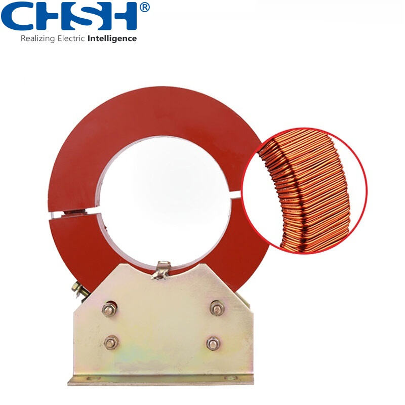
In modern power systems, accurate measurement and reliable protection are not optional — they are foundational requirements for safe, efficient, and uninterrupted electrical operation. At the heart of these capabilities lies a deceptively compact but critically important device: the current transformer. Whether deployed in high-voltage substations, industrial distribution panels, or utility metering systems, the current transformer plays a decisive role in translating large primary currents into safe, manageable secondary signals that protection relays, energy meters, and monitoring systems can process with precision.
Understanding how the current transformer improves both measurement accuracy and protection reliability requires looking at its operating principles, construction parameters, application context, and the specific ways it interfaces with the broader protection and metering infrastructure. This article provides a comprehensive technical and practical examination of how CTs fulfill their dual role in power systems — and why selecting and applying them correctly is essential for any serious power engineering project.
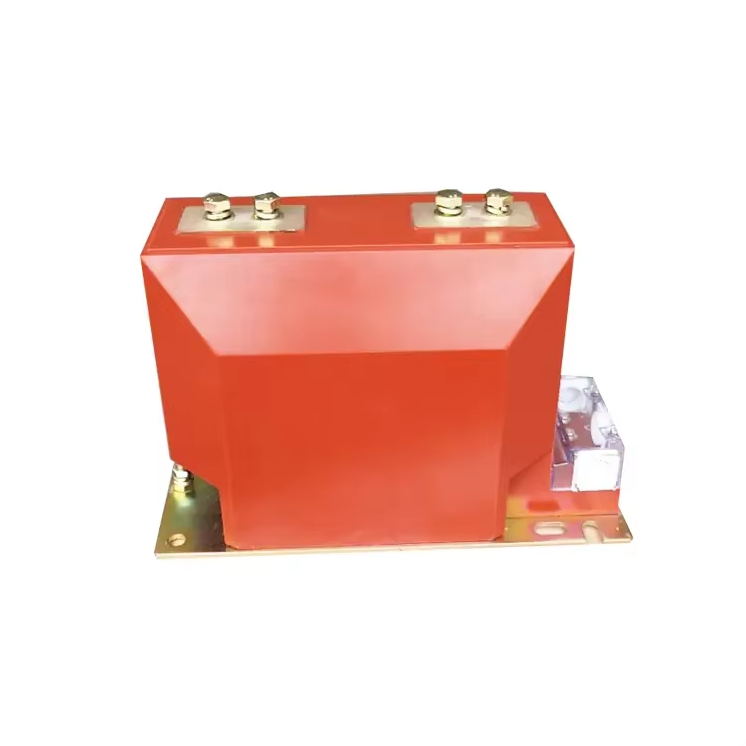
The Core Operating Principle of a Current Transformer
Electromagnetic Induction as the Foundation
A current transformer operates on the fundamental principle of electromagnetic induction. When alternating current flows through the primary conductor — which may be a single busbar pass-through or a wound primary winding — it generates a magnetic flux within the transformer core. This flux induces a proportional secondary current in the secondary winding, scaled according to the turns ratio. The result is a secondary current output that accurately mirrors the primary current waveform, reduced to a standard value such as 1 A or 5 A suitable for instrumentation input.
This proportional relationship is the key to measurement accuracy. Because the current transformer maintains a defined and highly stable ratio between primary and secondary currents, downstream devices can reconstruct the actual system current from the secondary signal with a known level of precision. The quality of this reproduction depends on core material properties, winding geometry, and the accuracy class designation assigned to the device during manufacturing and calibration.
In practice, no current transformer achieves a perfectly ideal ratio. There is always a small ratio error and phase displacement between primary and secondary currents. These deviations are quantified by the accuracy class — such as 0.2, 0.5, or 1 for metering, and 5P10 or 10P20 for protection — which defines the maximum allowable errors under specified burden and current conditions. Choosing the right accuracy class for each application is therefore the first step in ensuring system-wide measurement integrity.
Burden and Its Effect on Performance
The burden connected to the secondary terminals of a current transformer directly influences its ability to maintain accuracy. Burden refers to the total impedance presented by the secondary circuit, including connecting cables, relay inputs, and meter coils. If the burden exceeds the rated value for a given accuracy class, the current transformer will enter a saturated or overloaded condition in which its ratio error and phase angle error increase beyond acceptable limits.
Proper burden management is therefore a critical engineering task. Engineers must calculate the total secondary circuit impedance, account for cable resistance over the routing distance, and verify that the combined burden remains within the current transformer's rated VA output. When burdens are too high, accuracy degrades even when the CT itself is correctly specified. This is a frequent source of metering errors in field installations and highlights why the current transformer must be evaluated as part of a complete system, not in isolation.
How Current Transformers Enhance Measurement Accuracy
Metering Class CTs and Energy Billing Integrity
For revenue-grade energy metering, the current transformer must deliver exceptional ratio accuracy across a defined range of primary current — typically from 5% to 120% of rated current. Metering class CTs, designated with accuracy classes such as 0.2S, 0.5S, or 1, are engineered to minimize ratio error and phase displacement across this operating range. Even small inaccuracies in the CT's output translate directly into billing errors, which in commercial and industrial applications can represent significant financial consequences over time.
A well-designed metering current transformer uses a high-permeability core material — typically grain-oriented silicon steel or amorphous alloy — that maintains linear behavior well within its rated range. The secondary winding is wound with precision, and the entire assembly is characterized against calibrated reference standards. In revenue metering applications where regulatory compliance is required, the current transformer must be type-tested and certified according to standards such as IEC 61869-2 or ANSI C57.13.
For installations such as the current transformer designed for 10 kV systems, the construction integrates these accuracy requirements with the insulation demands of medium-voltage operation, ensuring that measurement quality is not compromised by the electrical stress environment in which the device operates.
Waveform Fidelity and Harmonic Accuracy
Modern power systems increasingly carry significant harmonic content due to the proliferation of variable frequency drives, power electronic converters, and non-linear loads. A current transformer that performs well at fundamental frequency (50 Hz or 60 Hz) may exhibit degraded accuracy when the primary current contains harmonics. This is because core losses and magnetizing impedance vary with frequency, introducing additional ratio errors at harmonic frequencies.
For applications where harmonic measurement matters — such as power quality monitoring, harmonic filtering control, or advanced energy management — the current transformer must be selected with attention to its frequency response characteristics. Some specialized CTs are designed with extended frequency response, maintaining accuracy up to several kilohertz. The core material choice and winding configuration both play roles in determining harmonic fidelity, and specifiers should request frequency response data from manufacturers when harmonic accuracy is a project requirement.
How Current Transformers Support Protection System Reliability
Protection Class CTs and Transient Behavior
Protection relays depend on the current transformer to faithfully reproduce fault currents that may be ten, twenty, or even fifty times the rated primary current. Unlike metering CTs, which are designed to saturate at a relatively low multiple of rated current to protect sensitive meter inputs, protection class current transformers are designed to remain linear — or at least within a predictable error limit — up to a specified accuracy limit factor (ALF). A protection current transformer rated 5P20, for example, maintains a composite error of no more than 5% at twenty times rated current.
This ability to handle overcurrent multiples without severe saturation is what enables protection relays to operate correctly during faults. If the current transformer saturates prematurely, the secondary signal becomes severely distorted, and the relay may fail to trip — or may trip with incorrect timing — with potentially catastrophic consequences for equipment and personnel safety. The protection current transformer therefore serves as a gatekeeper for fault current information, and its performance under extreme conditions defines the reliability boundaries of the entire protection scheme.
Transient response is another critical dimension of protection current transformer performance. During the first cycles of a fault, the primary current may contain a significant DC offset component that drives the core deep into saturation. This transient saturation can distort the secondary current waveform precisely at the moment when the relay most needs accurate input. Class P and Class PX current transformers are specified with different philosophies for managing this transient behavior, and system protection engineers must match the CT class to the relay type and the specific fault scenarios anticipated in the power system.
Differential and Distance Protection Schemes
In differential protection schemes for transformers, generators, and bus zones, the current transformer plays a particularly demanding role. Two or more CTs at different locations in the circuit must produce secondary currents that can be compared with sufficient accuracy to detect an internal fault while restraining from operating on external faults or inrush conditions. Any mismatch in CT ratio, phase angle, or saturation characteristics between the CTs in the differential scheme introduces an artificial differential current that can cause false tripping or reduce sensitivity to genuine faults.
Matching current transformers for differential protection requires attention to their magnetizing characteristics, expressed through the excitation curve or knee-point voltage. CTs used in the same differential zone should ideally have matched magnetizing curves to ensure that their secondary outputs track consistently under both normal and fault conditions. This is why protection engineers specify identical CT types, from the same manufacturer and batch where possible, when designing sensitive differential protection applications.
Distance protection relies on the current transformer to provide accurate current measurement in combination with voltage transformer inputs for impedance calculation. Ratio error and phase displacement in the current transformer introduce errors in the apparent impedance seen by the relay, which can shift zone boundaries and either cause under-reach or over-reach. High accuracy protection CTs help ensure that distance relay zones are set and maintained with the precision the protection philosophy demands.
Installation, Polarity, and Secondary Circuit Integrity
Correct Polarity and Phase Assignment
A current transformer must be installed with correct polarity orientation relative to its intended secondary circuit connections. The polarity markings — typically P1/P2 on the primary and S1/S2 on the secondary — define the phase relationship between primary and secondary currents. Reversing polarity introduces a 180-degree phase error in the secondary current, which will cause directional protection elements to operate in the wrong direction and energy meters to subtract rather than add consumed energy. Polarity errors are among the most common and consequential CT installation mistakes in the field.
Before commissioning any protection or metering system that relies on the current transformer, a polarity verification test should be performed. This can be done by injecting a known primary current and verifying the direction of secondary current flow against the expected polarity convention. Many modern secondary injection test sets include automated polarity verification routines, making this process straightforward even for complex multi-CT installations.
Open-Circuit Safety and Secondary Shorting
One of the most important safety rules governing current transformer operation is that the secondary terminals must never be left open-circuited while primary current is flowing. Unlike voltage transformers, where an open secondary is safe, an open-circuited current transformer secondary causes all the primary MMF to drive core flux to extreme levels. This results in a very high induced voltage at the secondary terminals — potentially thousands of volts — which is lethal to personnel and destructive to the CT insulation.
This characteristic demands that current transformer secondary circuits be designed with shorting facilities that allow technicians to safely disconnect relay or meter burdens without interrupting primary operation. Terminal blocks used with current transformer secondary circuits typically include integral shorting bars for this purpose. Compliance with this requirement is not optional — it is a fundamental safety requirement that every engineer and technician working with current transformers must understand and enforce.
Selecting the Right CT for Medium Voltage Applications
Voltage Class and Insulation Requirements
For medium voltage applications in the 6 kV to 35 kV range, the current transformer must be designed with insulation systems appropriate to the operating voltage level. The dielectric strength of the primary insulation, creepage distances, and impulse withstand ratings all scale with the voltage class. A current transformer rated for 10 kV systems, for example, must comply with the insulation levels specified in IEC 61869-2 for the Um = 12 kV equipment class, including both power frequency withstand and lightning impulse withstand levels.
The physical form factor of the current transformer also varies with voltage class. Ring-type or window CTs are common in lower voltage switchgear, while bar-primary or wound-primary designs with cast resin or oil-paper insulation are used in medium and high-voltage applications. The choice of construction type affects not only the insulation capability but also the ease of installation, maintenance access, and overall substation footprint.
Dual-Core and Multi-Ratio Designs for Flexibility
Many medium-voltage current transformers are manufactured with two or more independent cores within a single housing, allowing one core to serve metering functions while a separate core is dedicated to protection. This dual-core configuration ensures that the metering core can be optimized for accuracy within its normal operating range without compromising the protection core's ability to handle fault overcurrents. Separating the two functions into independent magnetic circuits avoids the compromises that would result from asking a single core to serve both accuracy classes simultaneously.
Multi-ratio current transformers provide additional flexibility by offering selectable turns ratios through secondary tap configurations. This is particularly useful in installations where the primary current may vary over time — for example, when load growth is expected — or where a single CT type needs to serve different ratio requirements in different panel positions. The ability to reconfigure the secondary ratio without replacing the CT reduces both capital cost and installation disruption.
FAQ
What is the difference between a metering CT and a protection CT?
A metering current transformer is optimized for ratio accuracy across the normal operating current range, typically from 5% to 120% of rated current, and is designed to saturate at relatively low overcurrent multiples to protect sensitive meter inputs. A protection current transformer, by contrast, is designed to maintain acceptable ratio performance at high multiples of rated current — such as 10 to 20 times rated — so that protection relays receive accurate fault current signals during system disturbances. The two types serve complementary but distinct purposes and should not be substituted for one another.
How does CT saturation affect protection relay performance?
When a current transformer saturates, its core flux reaches a limit beyond which additional primary current produces very little additional secondary current. The secondary waveform becomes severely clipped or distorted, causing the relay to see a much lower apparent current than is actually present on the primary. This can result in relay failure to trip during a fault, delayed tripping, or incorrect operation of protection elements that depend on waveform integrity such as directional or differential functions. Proper CT specification with an adequate accuracy limit factor prevents saturation under expected fault conditions.
Why must current transformer secondary circuits never be left open-circuited?
When primary current flows through a current transformer, the secondary circuit normally carries a proportional current that limits the core flux to a safe level. If the secondary is open-circuited, there is no opposing secondary MMF, and the core flux rises to saturation on every half-cycle, inducing a high-voltage spike at the secondary terminals. These voltages can reach thousands of volts and present a lethal risk to personnel and can destroy the CT insulation. All current transformer secondary circuits must be kept closed through appropriate burden or a shorting link when live work is performed.
What factors should be considered when selecting a current transformer for a 10 kV power system?
Key selection factors include the rated primary current, required accuracy class for both metering and protection, rated burden in VA, accuracy limit factor for the protection core, insulation level appropriate to 10 kV service, physical mounting and installation format, and compliance with applicable standards such as IEC 61869-2. The current transformer should also be evaluated for its transient performance if used in applications with high fault levels or fast protection relays. Dual-core designs are often preferred to serve both metering and protection requirements from a single installed unit.
Table of Contents
- The Core Operating Principle of a Current Transformer
- How Current Transformers Enhance Measurement Accuracy
- How Current Transformers Support Protection System Reliability
- Installation, Polarity, and Secondary Circuit Integrity
- Selecting the Right CT for Medium Voltage Applications
-
FAQ
- What is the difference between a metering CT and a protection CT?
- How does CT saturation affect protection relay performance?
- Why must current transformer secondary circuits never be left open-circuited?
- What factors should be considered when selecting a current transformer for a 10 kV power system?