
 EN
EN
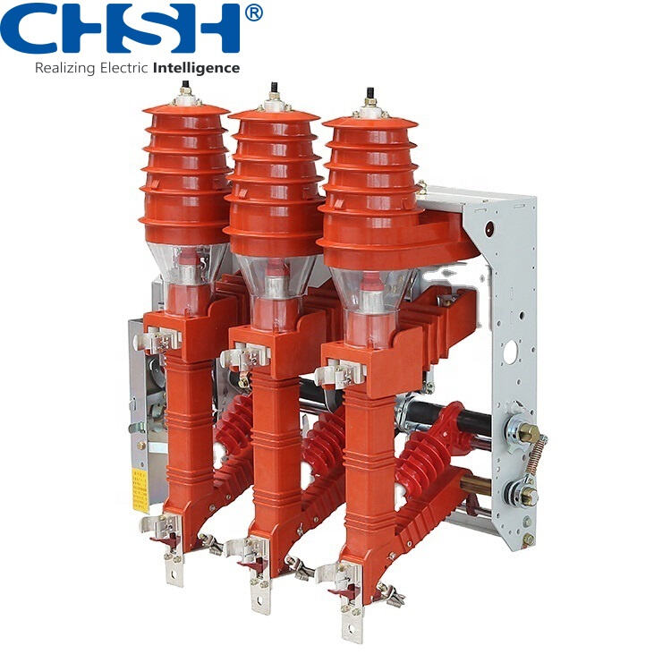
In any electrical system, protection is not an afterthought — it is a fundamental design requirement. Among the many protective devices used in power distribution and industrial installations, the fuse remains one of the most reliable, cost-effective, and widely deployed. Whether in low-voltage consumer circuits or high-voltage utility networks, the fuse serves as a critical line of defense against conditions that could otherwise cause catastrophic equipment damage, electrical fires, or complete system failure. Understanding exactly what protection functions a fuse provides helps engineers, facility managers, and procurement specialists make better decisions about system design and component selection.
The protection functions of a fuse are more nuanced than many people assume. A fuse does not simply interrupt current — it does so in a precisely calibrated way that accounts for current magnitude, duration, and the thermal characteristics of the protected circuit. Modern fuse technology, including high-voltage variants used in 33kV switchgear and isolation applications, is engineered to deliver multiple layers of protection within a single compact component. This article examines each of those protection functions in detail, explaining the mechanisms involved and the practical implications for electrical system safety and reliability.
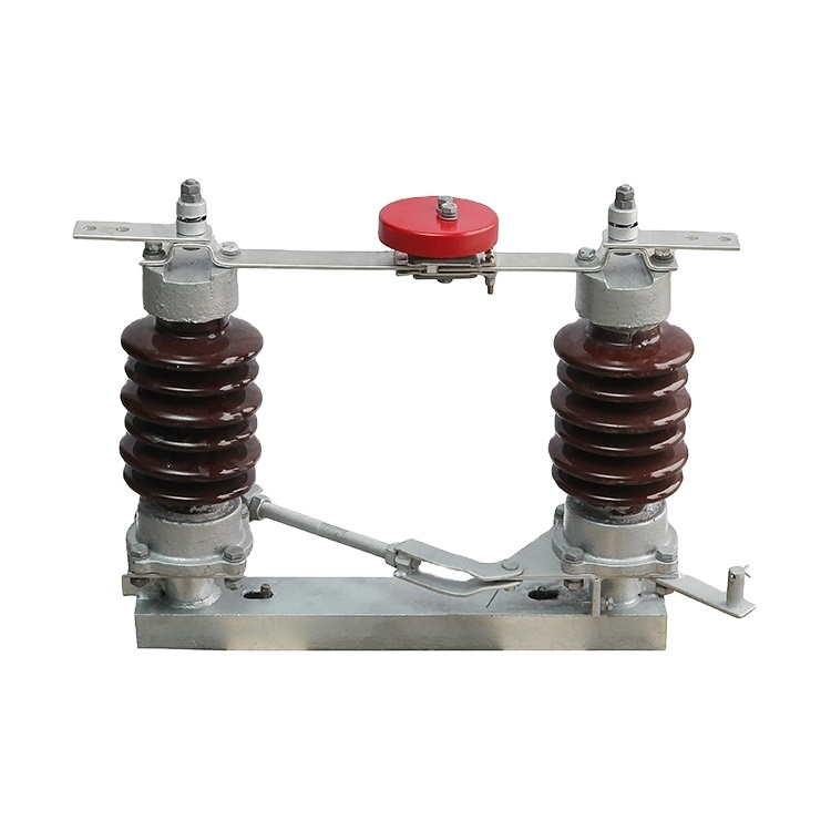
Overcurrent Protection: The Primary Function of a Fuse
How a Fuse Responds to Overcurrent Conditions
The most fundamental protection function of a fuse is overcurrent protection. When current flowing through a circuit exceeds the rated value of the fuse element, the element heats up due to resistive losses. If the overcurrent persists beyond a threshold determined by the fuse's time-current characteristic, the element melts and opens the circuit. This interruption stops the flow of current before the excess energy can damage conductors, insulation, or connected equipment.
The response of a fuse to overcurrent is not instantaneous for moderate overloads — it is intentionally time-delayed to allow temporary inrush currents, such as motor starting currents, to pass without unnecessary tripping. This inverse time characteristic means the fuse tolerates small overloads for longer periods but reacts very quickly to severe overcurrents. This behavior is a key advantage of the fuse over simpler protective devices that lack this graduated response.
In practical terms, overcurrent protection prevents conductor overheating, which is one of the leading causes of electrical fires in industrial and commercial installations. By interrupting the circuit before thermal damage accumulates, the fuse protects not just the immediate load but the entire upstream wiring and distribution infrastructure. This makes proper fuse sizing a critical step in any electrical system design.
Coordination with Upstream and Downstream Protective Devices
A well-designed protection scheme relies on coordination between multiple fuse elements and circuit breakers at different levels of the distribution hierarchy. The fuse closest to the fault should operate first, isolating only the affected section while leaving the rest of the system energized. This selectivity is achieved by choosing fuses with time-current characteristics that are properly graded from the load end back to the source.
When a fuse operates selectively, it minimizes the impact of a fault on the broader network. In industrial plants, this means a fault in one machine or feeder does not shut down an entire production line. In utility distribution networks, it means a fault on a lateral branch does not interrupt service to the main feeder. Achieving this level of coordination requires careful analysis of the time-current curves of every protective device in the system.
Short-Circuit Protection: Interrupting High Fault Currents
The Mechanics of Short-Circuit Interruption
Short-circuit protection is arguably the most demanding function a fuse must perform. During a bolted short circuit, fault currents can reach tens of thousands of amperes within milliseconds. The fuse must interrupt this current before it reaches its peak value — a capability known as current limiting. By melting and creating an arc that is rapidly extinguished within the fuse body, a current-limiting fuse prevents the full prospective fault current from ever flowing.
This current-limiting action has profound implications for system design. When a fuse limits the let-through current, it reduces the mechanical and thermal stress on all downstream equipment, including busbars, cable terminations, switchgear contacts, and transformers. Equipment can therefore be rated for lower fault levels, which reduces cost and complexity throughout the installation. The fuse effectively acts as a fault energy absorber, dissipating the energy within its own body rather than allowing it to propagate through the system.
High-voltage fuses, such as those used in 33kV applications alongside isolation switch disconnectors, must meet particularly stringent short-circuit interruption requirements. At these voltage levels, the arc energy involved in interrupting a fault is enormous, and the fuse design must ensure safe, reliable interruption without generating dangerous overvoltages or allowing arc re-ignition. The fuse used in such applications is typically filled with quartz sand or similar arc-quenching material to absorb arc energy and ensure clean interruption.
Protecting Transformers and Cables from Fault Damage
Transformers and power cables are among the most expensive and difficult-to-replace components in an electrical system. A fuse placed on the primary side of a distribution transformer provides essential protection against both internal transformer faults and external faults that could cause damaging fault currents to flow through the transformer windings. Without this protection, a fault could cause winding insulation to fail, leading to a transformer that requires rewinding or complete replacement.
Similarly, cable protection fuses are sized to ensure that the thermal withstand capability of the cable is never exceeded during a fault. The fuse's time-current characteristic must be coordinated with the cable's thermal damage curve so that the fuse always operates before the cable reaches its maximum permissible temperature. This coordination is a standard requirement in IEC and IEEE protection standards and is a core reason why the fuse remains a preferred protective device in cable-fed distribution systems.
Isolation and Disconnection Functions of a Fuse
Providing Visible Isolation After Operation
Beyond its protective functions, a fuse also provides a degree of isolation once it has operated. In many fuse designs, particularly high-voltage dropout fuses and fuse-isolation switch combinations, the operation of the fuse creates a visible open gap in the circuit. This visible isolation is important for maintenance safety, as it gives technicians a clear indication that the circuit is de-energized before they begin work on downstream equipment.
In high-voltage switchgear applications, the combination of a fuse with an isolation switch disconnector provides both fault interruption and safe isolation in a single assembly. The fuse handles the fault current interruption, while the disconnector provides the visible isolation gap required by safety regulations. This combination is widely used in medium and high-voltage distribution networks where both protection and safe working conditions must be ensured.
The ability of a fuse to provide post-operation isolation also simplifies fault finding. When a fuse has operated, the affected circuit is clearly identified, and the cause of the fault can be investigated before the fuse is replaced and the circuit re-energized. This sequential process — fault, isolation, investigation, restoration — is a key element of safe electrical system operation and is facilitated by the inherent characteristics of the fuse.
Supporting Safe Maintenance Procedures
In many industrial and utility installations, fuses are mounted in withdrawable or plug-in carriers that allow them to be removed without the use of tools, providing a convenient means of isolating individual circuits for maintenance. This feature makes the fuse not just a protective device but also a practical operational tool. Maintenance teams can quickly isolate a circuit by removing its fuse, perform the necessary work, and restore service by reinserting the fuse — all without the need for complex switching operations.
This ease of isolation is particularly valuable in environments where multiple circuits share a common distribution board or switchgear panel. The ability to isolate individual circuits independently, using the fuse as the isolation point, gives operators fine-grained control over which parts of the system are energized at any given time. It also reduces the risk of accidental energization during maintenance, which is a significant safety concern in high-voltage environments.
Earth Fault and Unbalanced Load Protection
Detecting and Interrupting Earth Fault Conditions
In three-phase systems, a fuse on each phase provides protection against earth faults — conditions where a live conductor makes unintended contact with earth or a grounded structure. When an earth fault occurs, the fault current flows through the affected phase fuse, which operates to interrupt the circuit. This prevents sustained earth fault current from flowing, which could cause fire, equipment damage, or electric shock hazards.
The effectiveness of a fuse in providing earth fault protection depends on the system earthing arrangement. In solidly earthed systems, earth fault currents are typically high enough to operate the fuse quickly. In impedance-earthed or isolated neutral systems, earth fault currents may be lower, and additional earth fault detection relays may be needed to supplement the fuse protection. Understanding the earthing arrangement is therefore essential when evaluating the earth fault protection capability of a fuse in any given application.
Responding to Phase Unbalance and Single Phasing
In three-phase motor circuits, the loss of one phase — known as single phasing — can cause the motor to draw excessive current on the remaining phases, leading to overheating and winding damage. A properly sized fuse on each phase will respond to the resulting overcurrent and interrupt the affected phase, preventing further damage. While dedicated motor protection relays provide more sophisticated protection against single phasing, the fuse provides a basic level of protection that is always present regardless of relay settings or auxiliary power availability.
Phase unbalance conditions, where the voltages or currents on the three phases are not equal, can also cause increased heating in motors and transformers. The fuse responds to the resulting overcurrent on the most heavily loaded phase, providing a degree of protection against sustained unbalanced operation. This function is particularly relevant in rural distribution networks where single-phase loads may create persistent unbalance conditions.
Thermal Protection and Equipment Preservation
Preventing Thermal Runaway in Sensitive Equipment
Many types of electrical equipment, including capacitors, semiconductors, and power electronics, are susceptible to thermal runaway — a condition where increasing temperature causes increasing current, which causes further temperature rise in a self-reinforcing cycle. A fuse placed in series with such equipment provides essential thermal protection by interrupting the circuit before the thermal runaway condition can develop to the point of equipment destruction or fire.
Semiconductor fuses, which are a specialized category of fuse designed for very fast operation, are specifically engineered to protect thyristors, diodes, and other power semiconductor devices. These devices have very limited thermal mass and can be destroyed in milliseconds by fault currents. The semiconductor fuse operates fast enough to interrupt the fault before the semiconductor junction temperature reaches its damage threshold, preserving expensive power electronic equipment that would otherwise require replacement.
Protecting Against Sustained Overload Conditions
Sustained overload conditions — where current exceeds the rated value by a moderate amount for an extended period — are a common cause of insulation degradation and premature equipment failure. A fuse with an appropriate time-current characteristic will operate under sustained overload conditions, interrupting the circuit before cumulative thermal damage becomes irreversible. This function is particularly important in applications where loads may gradually increase over time due to process changes or equipment additions.
The thermal memory of a fuse element means that repeated moderate overloads, even if each individual overload does not cause the fuse to operate, will progressively weaken the fuse element and eventually cause it to operate at a lower current than its nominal rating. This characteristic, while sometimes seen as a limitation, actually provides an additional layer of protection by ensuring that a fuse that has been repeatedly stressed will operate more readily, providing earlier warning of a developing overload condition.
FAQ
What is the difference between a fuse and a circuit breaker in terms of protection functions?
Both a fuse and a circuit breaker provide overcurrent and short-circuit protection, but they differ in their operating mechanism and reset capability. A fuse operates by melting its element, which must be replaced after operation. A circuit breaker uses an electromechanical mechanism that can be reset. Fuses generally offer faster operation and better current-limiting capability for high fault currents, while circuit breakers offer the convenience of resetting without replacement. In high-voltage applications, fuses are often preferred for their simplicity, reliability, and superior current-limiting performance.
How do I know if a fuse has operated in a high-voltage system?
In high-voltage systems, operated fuses are typically identified by visual indicators built into the fuse design, such as a striker pin that ejects when the fuse operates, or a dropout mechanism that causes the fuse to fall away from its mounting. In fuse-isolation switch assemblies, the operation of the fuse may also trigger a mechanical indicator on the switchgear panel. In all cases, the circuit should be treated as potentially energized until proper isolation and testing procedures have been completed, regardless of the visual indication.
Can a fuse provide protection against voltage surges or transients?
A standard fuse is not designed to protect against voltage surges or transients — its protection function is based on current, not voltage. Voltage surge protection requires dedicated devices such as surge arresters or transient voltage suppression components. However, in some fault scenarios where a voltage surge is accompanied by a sustained overcurrent, the fuse will operate in response to the overcurrent component of the fault. For comprehensive protection against both overcurrent and voltage transients, a fuse should be used in combination with appropriate surge protection devices.
What factors determine the correct fuse rating for a given application?
Selecting the correct fuse rating requires consideration of several factors: the normal operating current of the circuit, the maximum prospective fault current at the point of installation, the time-current characteristics required for coordination with other protective devices, the voltage rating of the system, and the breaking capacity required to safely interrupt the maximum fault current. In high-voltage applications, additional factors such as the system earthing arrangement, the type of load being protected, and the ambient temperature conditions must also be taken into account. Consulting the relevant IEC or IEEE standards and the fuse manufacturer's application guidelines is essential for correct selection.