
 EN
EN
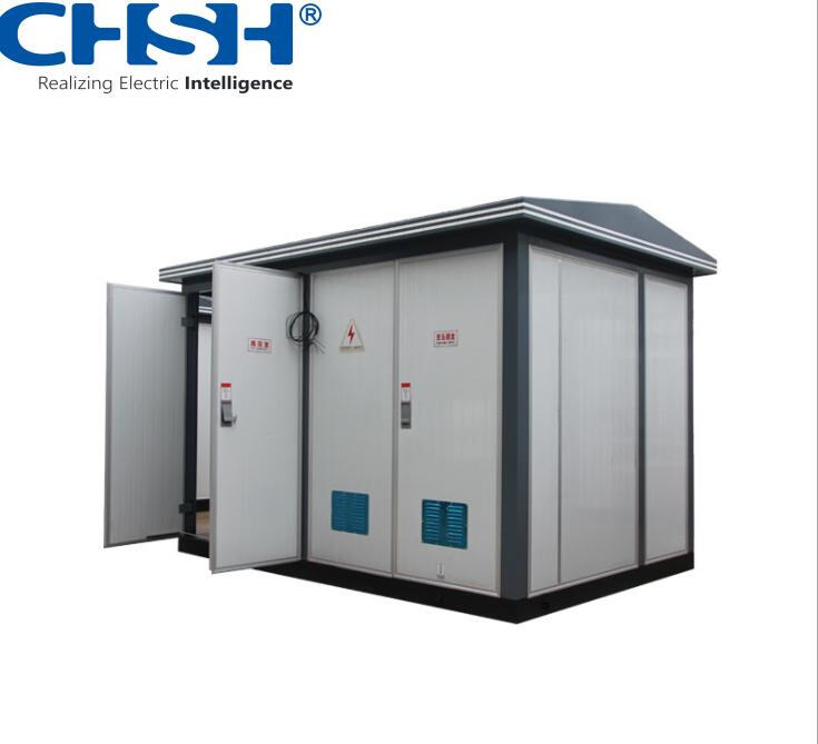
When engineers and project managers plan outdoor power distribution systems, one of the most critical decisions they face is how to integrate a transformer box into the overall infrastructure. Unlike indoor installations where environmental conditions are controlled, outdoor deployments demand a far more deliberate approach to placement, protection, connectivity, and long-term serviceability. The transformer box sits at the heart of voltage conversion and load management, making its integration a process that shapes the reliability and efficiency of the entire distribution network.
Understanding how a transformer box is integrated into outdoor power distribution projects requires looking beyond the unit itself. It involves site assessment, civil foundation work, high-voltage and low-voltage cable routing, protection coordination, grounding systems, and compliance with local grid codes. Each of these elements must be carefully sequenced and aligned to ensure the transformer box performs safely and consistently across its operational lifespan. This article walks through the full integration process, from pre-installation planning to commissioning and ongoing maintenance considerations.
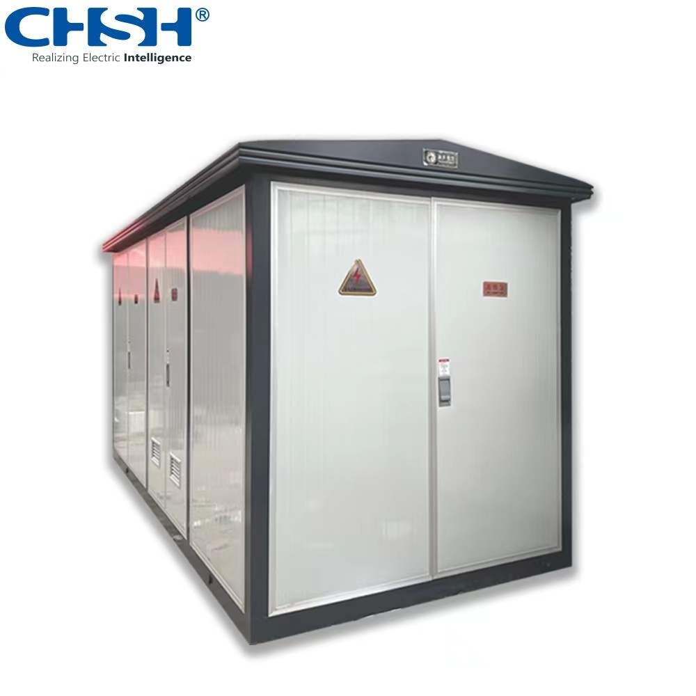
Site Assessment and Pre-Installation Planning
Evaluating the Physical Environment
Before a transformer box is ever delivered to a project site, engineers must conduct a thorough site assessment. This includes evaluating soil bearing capacity, flood risk, proximity to flammable materials, and prevailing wind and temperature conditions. Outdoor environments expose the transformer box to UV radiation, moisture ingress, temperature cycling, and potential physical impact, all of which influence the choice of enclosure rating and cooling method.
The assessment also considers clearance distances from buildings, fences, and public access areas. Most grid operators and national electrical codes specify minimum separation distances between a transformer box and adjacent structures. These clearances are not arbitrary — they exist to allow safe heat dissipation, emergency access, and arc flash containment in the event of a fault.
Soil resistivity testing is another key step, particularly for grounding system design. A transformer box installed in high-resistivity soil may require an extended ground electrode array to achieve the fault current dissipation levels required by the project specification. Skipping this step can lead to dangerous touch and step voltages during fault conditions.
Load Analysis and Transformer Sizing
Proper integration begins with accurate load analysis. Engineers calculate the total connected load, demand factor, and projected load growth to determine the correct kVA rating for the transformer box. Undersizing leads to overheating and premature failure, while oversizing increases capital cost and reduces efficiency at partial load.
For outdoor distribution projects serving industrial parks, residential developments, or renewable energy installations, the load profile can be complex. A transformer box may need to handle mixed loads including motors, lighting, HVAC systems, and sensitive electronic equipment. Each load type has different harmonic content and power factor characteristics that influence transformer selection and protection settings.
Voltage regulation requirements also factor into sizing decisions. If the distribution feeder is long or the load is highly variable, the transformer box may need on-load tap changer capability or a higher impedance rating to limit fault current contribution to the downstream network.
Civil Works and Foundation Installation
Designing the Concrete Pad or Plinth
The physical foundation of a transformer box installation is the concrete pad or plinth. This structure must be designed to support the full weight of the unit, including oil fill in the case of oil-immersed designs, and must remain stable under seismic loading where applicable. The pad is typically elevated slightly above grade to prevent surface water from pooling around the base of the transformer box.
Cable entry points are cast into the foundation during construction, allowing high-voltage and low-voltage cables to enter the transformer box from below in a protected conduit arrangement. This approach keeps cable terminations clean, reduces mechanical stress on conductors, and simplifies future cable replacement or addition.
For oil-immersed transformer box installations, a containment bund or oil sump is often required by environmental regulations. This structure captures any oil released during a leak or catastrophic failure, preventing soil and groundwater contamination. The bund volume is typically sized to hold at least 110% of the total oil volume in the unit.
Anchoring and Anti-Vibration Measures
Once the foundation is cured, the transformer box is positioned and anchored using hold-down bolts or restraint brackets. Proper anchoring prevents movement during seismic events, high winds, or accidental vehicle impact. In areas with significant seismic risk, the anchor design must comply with local building codes and may require engineering certification.
Anti-vibration pads are sometimes placed between the transformer box base and the concrete pad to reduce noise transmission into the ground and surrounding structures. This is particularly relevant in urban or suburban outdoor distribution projects where noise complaints from residents can become a compliance issue. The selection of pad material and thickness depends on the transformer's core and coil design and its rated noise level.
High-Voltage and Low-Voltage Cable Integration
Routing and Terminating HV Cables
Integrating a transformer box into an outdoor distribution network requires careful planning of the high-voltage cable route from the upstream substation or ring main unit. Cable sizing must account for continuous current rating, short-circuit withstand capability, and voltage drop over the route length. Cables are typically installed in buried ducts or direct-buried configurations depending on soil conditions and local utility standards.
At the transformer box, HV cables are terminated using heat-shrink or cold-shrink termination kits rated for the system voltage. The quality of these terminations is critical — a poorly made termination is one of the most common causes of premature cable failure and unplanned outages. Termination work is typically performed by certified jointers following manufacturer-approved procedures.
Where the transformer box is connected to a medium-voltage ring or radial feeder, the HV compartment will include load break switches or fuse-switch combinations that allow the unit to be isolated from the network without de-energizing the entire feeder. This switching capability is essential for safe maintenance access and fault isolation in a live distribution network.
Low-Voltage Distribution Board Connection
On the secondary side, the transformer box connects to a low-voltage distribution board or busbar chamber that feeds the downstream circuits. LV cables are sized for the full rated output current of the transformer, with additional capacity to handle inrush currents during motor starting or transformer energization. Cable routes from the transformer box to the LV board are kept as short as practical to minimize voltage drop and fault loop impedance.
The LV compartment of the transformer box typically houses the main circuit breaker or fused switch, metering current transformers, and surge protection devices. These components must be coordinated with the upstream HV protection to ensure selective fault clearance — meaning a fault on one LV circuit should trip only the affected circuit breaker, not the entire transformer box or the upstream feeder.
Protection, Grounding, and Control Integration
Protection Relay Coordination
A transformer box in an outdoor distribution project must be protected against overcurrent, earth fault, and in some cases differential faults. Protection relays are set based on the transformer's impedance, rated current, and the fault level available at the point of connection. Incorrect relay settings are a leading cause of either nuisance tripping or failure to clear genuine faults, both of which have serious operational consequences.
For distribution-class transformer box installations, overcurrent and earth fault protection is typically provided by fuses or electronic relays on the HV side, with thermal overload protection on the LV side. More sophisticated installations may include Buchholz relays for oil-immersed units, which detect gas accumulation caused by internal arcing or insulation breakdown before a catastrophic failure occurs.
Protection coordination studies are performed during the design phase to verify that the entire protection chain — from the upstream grid substation down through the transformer box to the final distribution circuits — operates selectively and within acceptable time limits. These studies are documented and submitted to the grid operator as part of the connection approval process.
Grounding System Design and Installation
The grounding system for a transformer box serves multiple purposes: it provides a reference potential for the LV neutral, limits touch and step voltages during fault conditions, and ensures reliable operation of earth fault protection. The design must comply with the applicable standard, whether that is IEC 60364, IEEE 80, or a national grid code requirement.
A typical outdoor transformer box grounding system consists of a buried copper conductor ring around the unit, connected to driven ground rods at intervals determined by the soil resistivity measurement. The transformer tank, LV neutral, and all metallic enclosures are bonded to this ring. Measured earth resistance values are recorded and compared against the project specification before the unit is energized.
In areas with high soil resistivity, chemical ground enhancement materials or deep-driven electrodes may be required to achieve the target resistance. The grounding system is one of the most safety-critical elements of the entire transformer box installation, and it must be verified by measurement before commissioning proceeds.
Commissioning and Handover
Pre-Energization Testing
Before a transformer box is energized for the first time in an outdoor distribution project, a comprehensive series of pre-energization tests must be completed. These include insulation resistance testing of HV and LV windings, turns ratio verification, vector group confirmation, and oil dielectric strength testing for oil-immersed units. Each test result is compared against factory test certificates and acceptance criteria defined in the project specification.
Cable insulation tests are performed on all HV and LV cables connected to the transformer box to verify that no damage occurred during installation. Protection relay settings are verified against the approved coordination study, and all interlocks and alarms are functionally tested. This systematic approach ensures that the transformer box and its associated systems are ready for safe energization.
Energization Sequence and Load Testing
The energization of a transformer box in an outdoor distribution project follows a defined sequence coordinated with the grid operator. The HV switch is closed first to energize the transformer on no-load, allowing the protection system to confirm that no internal faults are present. After a monitoring period, the LV main breaker is closed and load is progressively applied while voltage, current, and temperature readings are monitored.
Load testing confirms that the transformer box performs within its rated parameters under actual site conditions. Any deviations from expected voltage regulation, temperature rise, or noise levels are investigated and resolved before the unit is handed over to the asset owner. Commissioning records, including all test results and as-built drawings, are compiled into a handover package that forms the basis for future maintenance planning.
FAQ
What is the typical installation timeline for a transformer box in an outdoor distribution project?
The timeline varies depending on project complexity, but a typical outdoor transformer box installation from site preparation to commissioning takes between four and twelve weeks. Civil works, cable installation, and protection coordination studies are usually the longest phases. Prefabricated substation solutions can compress this timeline significantly by combining the transformer box, switchgear, and LV board into a factory-assembled unit.
How is a transformer box protected against flooding in outdoor installations?
Flood protection for an outdoor transformer box involves elevating the unit on a raised plinth, selecting an enclosure with an appropriate IP rating, and ensuring that cable entry points are sealed against water ingress. In high-risk flood zones, additional measures such as flood barriers, submersible-rated cable terminations, and remote monitoring systems may be specified to protect the transformer box and maintain supply continuity.
Can a transformer box be relocated after it has been installed outdoors?
Relocation of an outdoor transformer box is technically possible but involves significant work, including de-energization, cable disconnection, foundation demolition, and re-installation at the new site. Oil-immersed units require oil drainage and refilling, and all pre-energization tests must be repeated. Relocation is generally only justified when a major site reconfiguration makes the original position unsuitable for the long term.
What maintenance activities are required after a transformer box is integrated into an outdoor distribution network?
Routine maintenance for an outdoor transformer box includes periodic oil sampling and dielectric strength testing, infrared thermography of HV and LV connections, cleaning of insulators and bushings, verification of protection relay settings, and inspection of the grounding system. The frequency of these activities is determined by the asset owner's maintenance strategy, the criticality of the load served, and the manufacturer's recommendations for the specific transformer box model.
Table of Contents
- Site Assessment and Pre-Installation Planning
- Civil Works and Foundation Installation
- High-Voltage and Low-Voltage Cable Integration
- Protection, Grounding, and Control Integration
- Commissioning and Handover
-
FAQ
- What is the typical installation timeline for a transformer box in an outdoor distribution project?
- How is a transformer box protected against flooding in outdoor installations?
- Can a transformer box be relocated after it has been installed outdoors?
- What maintenance activities are required after a transformer box is integrated into an outdoor distribution network?